Ic 555 Timer Circuit Diagram
555 timer diagram ic block circuit ne555 controller configuration working op pins flop flip pwm discharge electrical resistive Build a simple push-on push-off circuit using 555 timer Schematic timer ic circuit diagram 6v converter 12v dc 회로 전자
GO LOOK IMPORTANTBOOK: IC 555 and CD 4047 measuring electronics
555 ic timer diagram circuit astable pinout pins block description multivibrator ic555 internal circuits ground explain structure figure functional its 555 timer ic pin diagram features and applications Schematic 555 timer circuit diagram / lm555 electronics schematic
555 ic timer circuit diagram
Go look importantbook: ic 555 and cd 4047 measuring electronicsDiagram led chaser 4017 555 circuit timer using wiring capacitor counter motor run start off ic phase electrosome mechanical shut 555 timer diagram internal ic astable circuit multivibrator monostable bistableTimer ic 555 tester.
555 timer tutorial: how it works and useful example circuitsAlternate switching relay timer circuit Timer ne555 engineeeringTimer ne555 pinout datasheet eleccircuit lm555 flop stable.

555 timer circuit electronics lambert
555 timer circuits blinking555 timer ic-block diagram-working-pin out configuration-data sheet Timer ne555 circuitsTimer 555 circuit led relay ic circuits switching off homemade alternate two projects alternating astable 220v mains board diagram switch.
Introduction to the 555 timer .


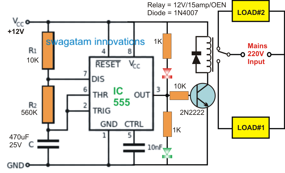
Alternate Switching Relay Timer Circuit

Schematic 555 Timer Circuit Diagram / LM555 Electronics Schematic

GO LOOK IMPORTANTBOOK: IC 555 and CD 4047 measuring electronics

555 Timer IC Pin Diagram Features And Applications | 555 Timer working

555 Timer Tutorial: How It Works and Useful Example Circuits

transistors - led chaser with non-mechanical shut-off option

555 Ic Timer Circuit Diagram | Free Download Wiring Diagram Schematic

555 Timer IC-Block Diagram-Working-Pin Out Configuration-Data Sheet

Introduction to the 555 Timer - Circuit Basics